The structure and working principle of the color profile
2 Characterization of three-channel input devices based on matrix conversion
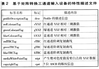
The characteristics of the three-channel input device based on the matrix conversion device description file contains the following tags (Table 2).

This conversion process is divided into two steps. The first is to convert the non-linear RGB values ​​to linear RGB values ​​using three channel tone-replicated curves, expressed as follows:
The value of linear R = redTRC [equipment R value] î™…
The value of linear G = redTRC [device G value] î™…
The value of linear B = redTRC [equipment B value] î™…
The second is to obtain a 3×3 matrix from the red, green, and blue three channels XYZ vs. tristimulus values, and use this matrix to convert the linear RGB values ​​to the relative XYZ values, which are expressed as follows:

Through the above conversion, the CIEXYZ tristimulus values ​​corresponding to this color can be obtained from the RGB values ​​of a group of input devices. Only when the connection space of the property file is CIEXYZ, the ICC color profile of the input device can use the above matrix/graded copy curve model curve. If the profile connection space is CIELAB, the multidimensional lookup table mode is used to convert from the device value to the profile file connection space. The multi-channel input device profile also uses a multidimensional lookup table mode to convert the device values ​​to the profile file connection space.
3 Multi-channel input device profile based on lookup table mode
The multi-channel input device profile based on the lookup table mode contains the tags shown in Table 3.

The label A2B0 is a color lookup table from the device's color space to the color space, and is divided into 8-bit and 16-bit data types. The data for this type of tag consists of the following four parts:
 3×3 ​​matrix  only for input data XYZ;
 1 set of 1-dimensional input lookup table;
 1 multidimensional lookup table;
 1 set of 1D output lookup table.
When performing color conversion through such data, the data processing sequence is: 3×3 matrix → one-dimensional input lookup table → multidimensional lookup table → one-dimensional output lookup table.
For an input device, given the RGB value for a color, the LAB value for that color can be obtained by reading the A2B0 tag. (to be continued)
Solid Door,Timber Door,Interior Door
Bathroom Vanity Co., Ltd. , http://www.cnaluminumwindow.com